

The essential answer
A resistance measurement can include the specimen, its contacts, and the connecting leads. Contact resistance depends on the actual current path through the interface, not merely the apparent overlap area. Pressure, surface films, roughness, and contact geometry can change it. Four-terminal sensing can reduce the contribution of current-carrying lead and contact voltage drops when implemented appropriately, but it does not automatically remove every geometric or thermal error. State where current enters and where voltage is sensed before interpreting a measured resistance as a bulk material property.
How to reason about it
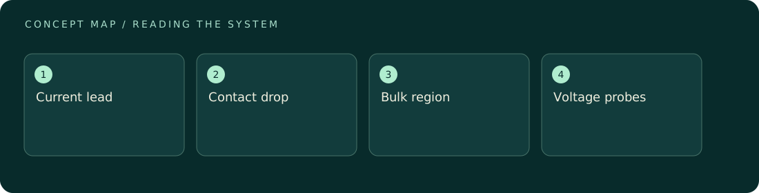
In a two-terminal measurement, the same connections carry current and sense voltage, so their drops are included in the inferred resistance. In a four-terminal arrangement, separate voltage probes draw negligible current and measure a selected portion of the sample. This can isolate the intended region, provided probe placement and current distribution are suitable. Small signals can also contain thermoelectric offsets; reversing current and comparing voltages helps distinguish a current-dependent drop from a stable offset. Excess current can heat the contact and change its resistance during measurement. Repeated clamping or pressure variation can reveal a contact-sensitive result, although it may also change a soft specimen. Treat contact preparation as part of the experiment: cleaning method, force, time after assembly, and environmental exposure should be documented when they materially influence the reading.
ILLUSTRATIVE · NOT A REPORTED RESULT
An example to work through
Assume a hypothetical sample has 1 ohm bulk resistance, each of two contacts adds 0.4 ohm, and leads add 0.2 ohm total. A two-terminal test reads 2 ohms, twice the bulk value. At 10 mA the complete voltage drop is 20 mV, while ideal voltage probes across only the uniform bulk region would read 10 mV. This example assumes ohmic behavior, negligible voltage-probe current, uniform current distribution, and no heating. A real four-terminal geometry still requires checking whether the sensed region represents the property being claimed.
Where interpretation fails
A low measured resistance after tightening a clamp may reflect improved contact rather than a changed material. Four wires alone do not guarantee a valid bulk measurement if the voltage probes sample a nonuniform current region or bypass part of the intended path. Draw the geometry explicitly.
The next decision
Use separate current and voltage connections for low-resistance work when practical. Test current reversal, current magnitude, and contact reproducibility. If the result changes strongly with contact conditions, report an assembly resistance until the bulk and interface contributions have been convincingly separated by geometry or modeling.
Sources & context
These sources support the concepts noted below. Our synthetic examples and research framing are educational interpretation; they are not findings from these organizations or validation of our ventures.
- Influence of surface roughness and waviness upon thermal contact resistance — NASA ↗
Primary report context for interface geometry affecting transport; electrical example is an independent circuit calculation.
Source check: NASA technical-report bibliographic/search excerpt reviewed.
Educational research context, not a validated device specification or clinical protocol. Read our editorial and correction policy.