
The essential answer
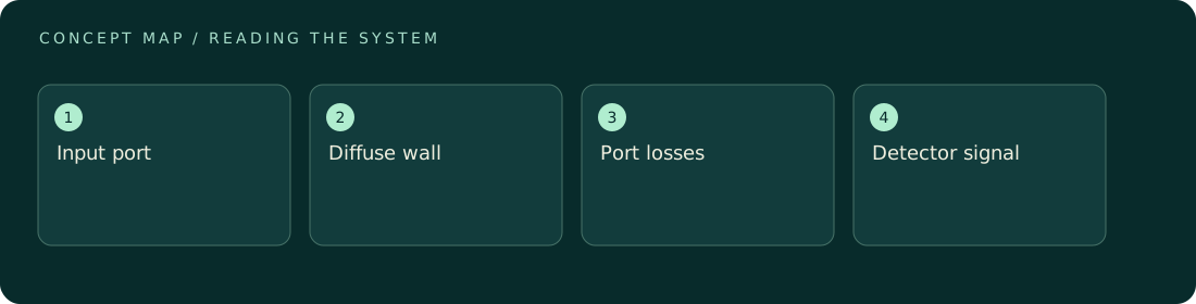
An integrating sphere uses repeated diffuse reflections inside a cavity to make detector response less sensitive to the exact direction and shape of entering light. It is useful for total power and diffuse reflection or transmission measurements. It does not automatically collect all light or remove calibration requirements. Port losses, coating reflectance, baffles, wavelength response, and the sample itself affect the conversion from detector signal to optical power. Treat the sphere and detector as a calibrated system in the geometry actually used.
How to reason about it
Light entering the sphere spreads through repeated reflections, and a detector samples part of the resulting radiance. Direct illumination of the detector or an unsuitable baffle can undermine the intended averaging. Opening a port changes the effective wall loss; inserting a dark sample can also change the sphere's throughput. This substitution effect means a reference and test sample can create different internal conditions even under the same input power. Coating properties vary with wavelength and can change through contamination or damage. Highly specular samples require care because their first reflection may escape through a port before mixing. For a reflectance measurement, specify whether the specular component is included or excluded. Match calibration and use conditions, monitor source drift, and check linearity across the power range. A sphere improves angular collection but does not by itself supply angular information needed for a vector momentum calculation.
ILLUSTRATIVE · NOT A REPORTED RESULT
An example to work through
Assume an illustrative calibrated sphere-detector system gives 2.0 V for 10 mW under a fixed geometry, a sensitivity of 0.20 V/mW. A test signal of 1.4 V would indicate 7 mW after dark subtraction. Now suppose inserting the sample reduces throughput by 5%, so the actual sensitivity becomes 0.19 V/mW. Using the original calibration underestimates power: 1.4/0.19 = 7.37 mW. The numerical correction is only illustrative; real substitution corrections require characterization of the sphere, sample, and ports rather than assuming a universal percentage.
Where interpretation fails
Do not confuse angular averaging with perfect angular independence. A beam aimed into a port, a specular escape path, or direct detector illumination can change the response substantially. A sphere that measures total scattered power also discards the angular distribution, so it cannot alone determine the force from that scattering.
The next decision
Use a sphere when incomplete collection of diffuse light dominates the uncertainty. Validate the selected port and baffle configuration with representative beams or samples, and retain wavelength-specific calibration. For force accounting, pair total-power collection with angular measurements or a justified scattering model instead of assuming all scattered momentum cancels.
Sources & context
These sources support the concepts noted below. Our synthetic examples and research framing are educational interpretation; they are not findings from these organizations or validation of our ventures.
- Thorlabs: General-Purpose Integrating Spheres ↗
Manufacturer search excerpt identifies substitution-error discussion; PDF open returned no extractable text.
Source check: Relevant excerpt checked; original illustrative calculation, not source data.
Educational research context, not a validated device specification or clinical protocol. Read our editorial and correction policy.